7C-8J, I. S. Gajra Industrial Area - 1, A.B. Road,
Dewas - 455001 M.P. INDIA
 Email info@fluidomat.com
Dewas - 455001 M.P. INDIA
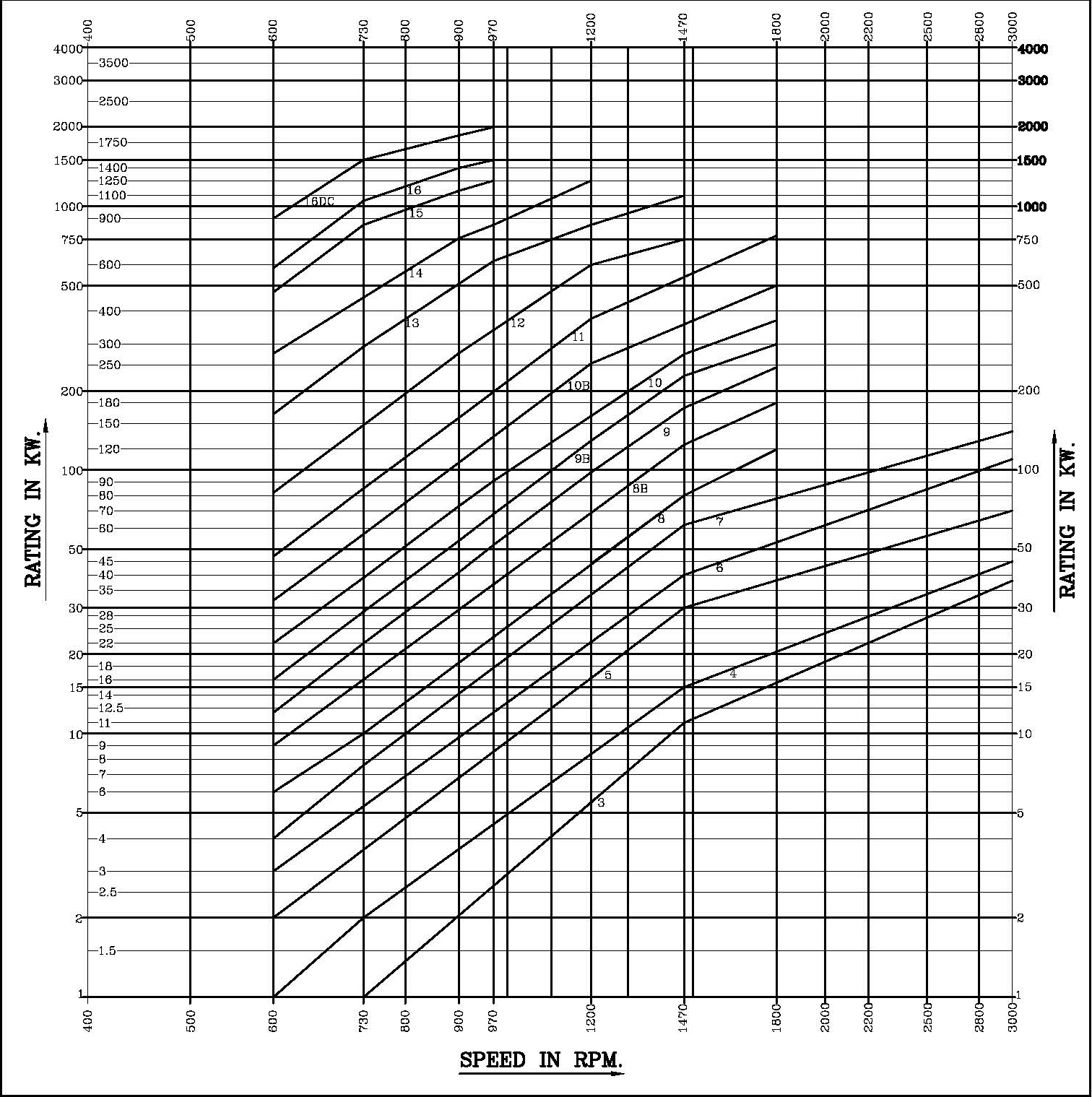
| COUPLING MODEL SM,SMD,SM-DX | Maximum Ratings in KW at Different Input Speeds RPM. | ||||||||
|---|---|---|---|---|---|---|---|---|---|
| 600 RPM | 730 RPM | 900 RPM | 970 RPM | 1200 RPM | 1470 RPM | 1800 RPM | *3000 RPM | *3600 RPM | |
| 1 | –– | 0.5 | 0.9 | 1.2 | 2.2 | 4 | 7.5 | 20 | 26 |
| 2 | –– | 0.9 | 1.7 | 2.2 | 4.1 | 7.5 | 13.7 | 30 | 36 |
| 3 | –– | 1.3 | 2.4 | 3 | 6 | 11 | 18 | 38 | 45 |
| 4 | 1 | 2 | 4 | 5 | 9 | 16.5 | 22 | 45 | –– |
| 5 | 2 | 4 | 7 | 9 | 16.3 | 30 | 42 | 70 | –– |
| 6 | 3 | 5 | 9 | 11 | 22 | 40 | 60 | 110 | –– |
| 7 | 4 | 8 | 15 | 18 | 34 | 62 | 85 | 140 | –– |
| 8 | 6 | 10 | 18 | 23 | 44 | 80 | 120 | –– | –– |
| 8 B | 9 | 16 | 29 | 36 | 68 | 125 | 180 | –– | –– |
| 9 | 12 | 22 | 41 | 52 | 98 | 172 | 246 | –– | –– |
| 9 B | 16 | 29 | 54 | 68 | 129 | 228 | 300 | –– | –– |
| 10 | 22 | 39 | 73 | 91 | 172 | 275 | 370 | –– | –– |
| 10 B | 32 | 57 | 107 | 134 | 253 | 373 | 500 | –– | –– |
| 11 | 47 | 85 | 158 | 198 | 374 | 525 | 775 | –– | –– |
| 12 | 82 | 148 | 278 | 348 | 600 | 750 | –– | –– | –– |
| 13 | 163 | 293 | 550 | 620 | 850 | 1100 | –– | –– | –– |
| 14 | 277 | 500 | 758 | 850 | 1250 | –– | –– | –– | –– |
| 15 | 472 | 850 | 1148 | 1250 | –– | –– | –– | –– | –– |
| 16 | 583 | 1050 | 1400 | 1500 | –– | –– | –– | –– | –– |
| 16 DC | 900 | 1500 | 1862 | 2000 | –– | –– | –– | –– | –– |
*Coupling for 3000 & 3600 RPM should be selected only after our approval is obtained.
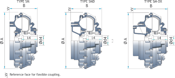
| SM,SMD,SM-DX | ø A | B | ød4 max | ød4 max | ᶩ 4 max | * Dry Weight | Max. Oil Filling In Litres | Threads 'M'* for Coupling | Connected Flexible Coupling Model | ||||||
|---|---|---|---|---|---|---|---|---|---|---|---|---|---|---|---|
| SM | SMD | SM-DX | SM | SMD | SMD-DX | SM | SMD | SMD-DX | |||||||
| 1 | 295 | 147 | - | - | 38 | - | 86 | 24 | - | - | 1.9 | - | - | 3/4" BSW | FXC-I |
| 2 | 328 | 153 | - | - | 48 | - | 90 | 27 | - | - | 2.8 | - | - | 3/4" BSW | FFX1 |
| 3 | 342 | 158 | 213 | 247 | 42 | 28 | 80 | 27 | 30 | 32 | 2.9 | 3.9 | 4.3 | 3/4" BSW | FFX-1 |
| 4 | 367 | 160 | 215 | 249 | 50 | 36 | 90 | 30 | 34 | 35 | 3.8 | 4.3 | 4.6 | 3/4" BSW | FFX-1 |
| 5 | 406 | 190 | 220 | 280 | 65 | 50 | 110 | 40 | 44 | 45 | 4.9 | 5.8 | 6.7 | 1" BSW | FFX-2 |
| 6 | 435 | 213 | 239 | 310 | 70 | 53 | 120 | 55 | 59 | 61 | 6.5 | 7.7 | 9.6 | 1" BSW | FFX-3 |
| 7 | 471 | 218 | 263 | 333 | 80 | 63 | 135 | 66 | 71 | 73 | 8 | 9.4 | 11.3 | 1" BSW | FFX-3 |
| 8 | 505 | 238 | 279 | 359 | 80 | 63 | 140 | 77 | 83 | 85 | 9.7 | 11.5 | 14.8 | 1" BSW | FFX-4 |
| 8 B | 553 | 250 | 290 | 380 | 95 | 70 | 155 | 96 | 102 | 105 | 14.5 | 16.1 | 19.1 | 1 1/4" BSW | FFX-4 |
| 9 | 584 | 255 | 305 | 385 | 95 | 80 | 155 | 104 | 110 | 113 | 16.1 | 19.3 | 20.8 | 1 1/4" BSW | FFX-4 |
| 9 B | 620 | 270 | 335 | 430 | 95 | 80 | 160 | 150 | 165 | 168 | 19.4 | 21.5 | 24.7 | 1 1/2" BSW | FP-1/FFX-5 |
| 10 | 644 | 280 | 329 | 424 | 110 | 85 | 170 | 170 | 180 | 185 | 25.1 | 28.1 | 33.9 | 1 1/2" BSW | FP-1/FFX-5 |
| 10 B | 714/td> | 310 | 355 | 451 | 110 | 85 | 190 | 210 | 225 | 230 | 31.8 | 36.5 | 45.4 | 1 1/2" BSW | FP-2A |
| 11 | 751 | 320 | 375 | 471 | 120 | 100 | 200 | 254 | 268 | 273 | 37.1 | 42.9 | 49 | # Ø50-8P | FP-2A |
| 12 | 845 | 359 | 435 | 555 | 130 | 110 | 240 | 310 | 345 | 355 | 51.3 | 65.6 | 71.5 | # Ø50-8P | FP-2B |
| 13 | 960 | 441 | 489 | 619 | 150 | - | 270 | 440 | 480 | 495 | 72.4 | 91.3 | 106.6 | # Ø50-8P | FP-3 |
| 14 | 1104 | 451 | 494 | 624 | 160 | - | 275 | 682 | 730 | 745 | 114.7 | 131.9 | 153.9 | # Ø65-16P | FP-4B |
| 15 | 1230 | 485 | 594 | 724 | 160 | - | 275 | 850 | 920 | 940 | 147.6 | 181.4 | 193.1 | # Ø75-16P | FP-4B |
| 16 | 1298 | 586 | 668 | 798 | 190 | - | 320 | - | 1250 | - | 189.2 | 241.7 | 268.4 | # Ø75-16P | ** |
| **16 DC | 1298 | 831 | - | - | 190 | - | 320 | - | 1800 | - | - | - | - | # Ø75-16P | ** |
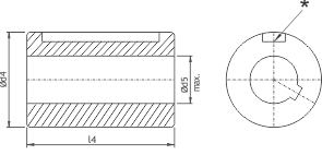
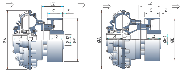
| Model SM-SMD-SM-DX | Internal Hub | Internal Hub | ||||
|---|---|---|---|---|---|---|
| Фd1 max. | Фd1 max. | l1 | Фd2 max. | l2 max. | l2 | |
| 3,4 | 48 | 67 | 67 | 60 | 75 | 130 |
| 5 | 60 | 72 | 72 | 75 | 90 | 150 |
| 6,7 | 80 | 92 | 72 | 90 | 110 | 170 |
| 8,8B,9 | 90 | 102 | 87 | 100 | 120 | 195 |
| 9B,10 | - | - | - | 125 | 150 | 230 |
| Model SM-SMD-SM-DX | Pad Type Coupling | ||
|---|---|---|---|
| Фd3 max. | l3 | l3 | |
| 9B, 10 | 100 | 110 | 120 |
| 10B,11 | 120 | 140 | 151 |
| 12 | 140 | 155 | 167 |
| 13 | 160 | 180 | 179 |
| 14 | 160 | 180 | 194 |
| 15,16 | 180 | 200 | 214 |
| Flexible Coupling Model | Spider Type Coupling | ||||
|---|---|---|---|---|---|
| øE | C | Z | ᶩ 2 | L2 | |
| FFX-1 | 200 | 75 | 20 | 75 | 130 |
| 250 | 95 | 0 | 75 | 130 | |
| FFX-2 | 250 | 95 | 20 | 90 | 150 |
| 300 | 118 | 5 | 90 | 158 | |
| 315 | 118 | 5 | 90 | 158 | |
| FFX-3 | 300 | 118 | 17 | 110 | 170 |
| 315 | 118 | 17 | 110 | 170 | |
| 400 | 150 | 5 | 110 | 190 | |
| FFX-4 | 300 | 118 | 42 | 120 | 195 |
| 315 | 118 | 42 | 120 | 195 | |
| 400 | 150 | 10 | 120 | 195 | |
| 500 | 190 | 5 | 120 | 230 | |
| *FFX-5 | 400 | 150 | 29 | 150 | 230 |
| 500 | 190 | 5 | 150 | 246 | |
* For fluid Coupling Model SM/SMD/SM-DX - 9B & 10.
| Model | Outer Wheel | Inner Wheel |
|---|---|---|
| SM-3 | 0.22 | 0.04 |
| SM-4 | 0.33 | 0.06 |
| SM-5 | 0.68 | 0.21 |
| SM-6 | 0.89 | 0.24 |
| SM-7 | 1.32 | 0.34 |
| SM-8 | 1.72 | 0.37 |
| SM-8B | 2.4 | 0.64 |
| SM-9 | 2.82 | 0.75 |
| SM-9B | 4.65 | 1.53 |
| SM-10 | 5.01 | 1.72 |
| SM-10B | 10.15 | 2.9 |
| SM-11 | 11.66 | 3.41 |
| SM-12 | 18.3 | 5.56 |
| SM-13 | 35.74 | 12.22 |
| SM-14 | 61.55 | 21.7 |
| SM-15 | 93.13 | 33.7 |
| Model | Outer Wheel | Inner Wheel |
| SMD-3 | 0.23 | 0.04 |
| SMD-4 | 0.35 | 0.06 |
| SMD-5 | 0.71 | 0.21 |
| SMD-6 | 0.97 | 0.24 |
| SMD-7 | 1.47 | 0.34 |
| SMD-8 | 1.85 | 0.39 |
| SMD-8B | 2.61 | 0.67 |
| SMD-9 | 3.06 | 0.78 |
| SMD-9B | 5.09 | 1.58 |
| SMD-10 | 6.07 | 1.79 |
| SMD-10B | 11.3 | 3 |
| SMD-11 | 12.97 | 3.55 |
| SMD-12 | 20.33 | 5.86 |
| SMD-13 | 39.82 | 12.75 |
| SMD-14 | 68.04 | 22.56 |
| SMD-15 | 102.7 | 35.07 |
| SMD-16 | 162 | 54.1 |
| Model | Outer Wheel | Inner Wheel |
| SMDX-3 | 0.24 | 0.04 |
| SMDX-4 | 0.36 | 0.06 |
| SMDX-5 | 0.74 | 0.21 |
| SMDX-6 | 1.04 | 0.24 |
| SMDX-7 | 1.59 | 0.34 |
| SMDX-8 | 1.96 | 0.39 |
| SMDX-8B | 2.76 | 0.67 |
| SMDX-9 | 3.24 | 0.78 |
| SMDX-9B | 5.55 | 0.58 |
| SMDX-10 | 7.04 | 1.79 |
| SMDX-10B | 12.3 | 3 |
| SMDX-11 | 14.07 | 3.55 |
| SMDX-12 | 21.93 | 5.86 |
| SMDX-13 | 43.02 | 12.75 |
| SMDX-14 | 73.14 | 22.56 |
| SMDX-15 | 110.7 | 35.07 |