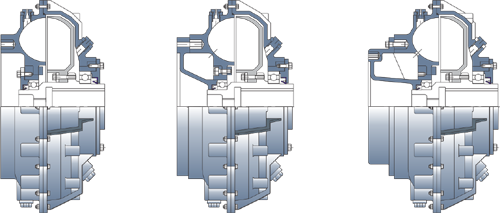
Type SM / SMD / SM-DX
Hollow-shaft compact couplings — basic, delayfil (SMD) and extended-delayfil (SM-DX) executions.
Constant-fill, fixed-speed coupling in three circuit types.
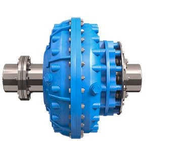
The Fluidomat Type SM family is a hollow-shaft, compact constant-fill fluid coupling with a rubber flexible coupling on the end. To satisfy the starting and running characteristics of industrial machines, it is offered in three circuit types that bring the starting torque down to as low as 120% of nominal torque.
Type SM (and HF) is the basic coupling without a delayfil chamber, with starting torque adjustable in the range of 180% to 275%. Type SMD (and HFD) adds a delayfil chamber for a wider 150% to 275% range. Type SM-DX (and HF-DX) uses an extended delayfil chamber for the gentlest start of all, 120% to 270%.
Normal operating slip is just 2% to 5% depending on coupling size and starting-torque value. A fusible plug protects against sustained overload, and the coupling is suitable for two consecutive starts from hot and three from cold.
Key data
Built for the duty, finished to order
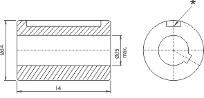
Coupling types SM/SMD/SM-DX are supplied with finished bores on the fluid-coupling shaft. Where finished bores cannot be specified at the time of ordering, a separate shaft bush is provided.
- Three circuit types — SM, SMD and SM-DX — to match any starting and running characteristic
- Starting torque adjustable down to 120% of nominal for soft starting of high-inertia loads
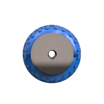
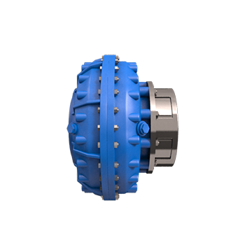
- Hollow-shaft compact design with a rubber flexible coupling on the output end
- Low normal operating slip of 2% to 5% for efficient running
- Fusible plug blows off at 130°C as standard; 160°C available as an option
- Rated for two consecutive starts from hot and three from cold
- Supplied in finished bores; separate shaft bush available when bores cannot be specified at ordering
- Maximum permissible bore in the shaft bush is denoted Ød5 in the dimension table
Rating table — SM / SMD / SM-DX
Maximum ratings in KW at different input speeds (RPM). Couplings for 3000 and 3600 RPM should be selected only after Fluidomat approval is obtained.
| Model | 600 | 730 | 900 | 970 | 1200 | 1470 | 1800 | 3000* | 3600* |
|---|---|---|---|---|---|---|---|---|---|
| 1 | — | 0.5 | 0.9 | 1.2 | 2.2 | 4 | 7.5 | 20 | 26 |
| 2 | — | 0.9 | 1.7 | 2.2 | 4.1 | 7.5 | 13.7 | 30 | 36 |
| 3 | — | 1.3 | 2.4 | 3 | 6 | 11 | 18 | 38 | 45 |
| 4 | 1 | 2 | 4 | 5 | 9 | 16.5 | 22 | 45 | — |
| 5 | 2 | 4 | 7 | 9 | 16.3 | 30 | 42 | 70 | — |
| 6 | 3 | 5 | 9 | 11 | 22 | 40 | 60 | 110 | — |
| 7 | 4 | 8 | 15 | 18 | 34 | 62 | 85 | 140 | — |
| 8 | 6 | 10 | 18 | 23 | 44 | 80 | 120 | — | — |
| 8 B | 9 | 16 | 29 | 36 | 68 | 125 | 180 | — | — |
| 9 | 12 | 22 | 41 | 52 | 98 | 172 | 246 | — | — |
| 10 | 22 | 39 | 73 | 91 | 172 | 275 | 370 | — | — |
| 10 B | 32 | 57 | 107 | 134 | 253 | 373 | 500 | — | — |
| 11 | 47 | 85 | 158 | 198 | 374 | 525 | 775 | — | — |
| 12 | 82 | 148 | 278 | 348 | 600 | 750 | — | — | — |
| 13 | 163 | 293 | 550 | 620 | 850 | 1100 | — | — | — |
| 16 | 583 | 1050 | 1400 | 1500 | — | — | — | — | — |
| 16 DC | 900 | 1500 | 1862 | 2000 | — | — | — | — | — |
* Couplings for 3000 and 3600 RPM should be selected only after our approval is obtained. Full technical specification, dimension tables, dry weights and oil quantities are given in the sections below.
Type SM / SMD / SM-DX
Hollow-shaft compact constant-fill coupling — SMD adds a delayfil chamber and SM-DX an extra-long delayfil chamber, with a rubber (flexible) coupling on the input end.

Technical specification & dimension table
Overall and mounting dimensions (mm), dry weights and oil filling for the SM, SMD and SM-DX executions. The minimum bore d4 should exceed the withdrawal-bolt diameter M by at least 2 mm.
| SM,SMD,SM-DX | ø A | B | ød4 max | ød4 max | Ø 4 max | * Dry Weight | Max. Oil Filling In Litres | Threads 'M'* for Coupling | Connected Flexible Coupling Model | ||||||
|---|---|---|---|---|---|---|---|---|---|---|---|---|---|---|---|
| SM | SMD | SM-DX | SM | SMD | SMD-DX | SM | SMD | SMD-DX | |||||||
| 1 | 295 | 147 | - | - | 38 | - | 86 | 24 | - | - | 1.9 | - | - | 3/4" BSW | FXC-I |
| 2 | 328 | 153 | - | - | 48 | - | 90 | 27 | - | - | 2.8 | - | - | 3/4" BSW | FFX1 |
| 3 | 342 | 158 | 213 | 247 | 42 | 28 | 80 | 27 | 30 | 32 | 2.9 | 3.9 | 4.3 | 3/4" BSW | FFX-1 |
| 4 | 367 | 160 | 215 | 249 | 50 | 36 | 90 | 30 | 34 | 35 | 3.8 | 4.3 | 4.6 | 3/4" BSW | FFX-1 |
| 5 | 406 | 190 | 220 | 280 | 65 | 50 | 110 | 40 | 44 | 45 | 4.9 | 5.8 | 6.7 | 1" BSW | FFX-2 |
| 6 | 435 | 213 | 239 | 310 | 70 | 53 | 120 | 55 | 59 | 61 | 6.5 | 7.7 | 9.6 | 1" BSW | FFX-3 |
| 7 | 471 | 218 | 263 | 333 | 80 | 63 | 135 | 66 | 71 | 73 | 8 | 9.4 | 11.3 | 1" BSW | FFX-3 |
| 8 | 505 | 238 | 279 | 359 | 80 | 63 | 140 | 77 | 83 | 85 | 9.7 | 11.5 | 14.8 | 1" BSW | FFX-4 |
| 8 B | 553 | 250 | 290 | 380 | 95 | 70 | 155 | 96 | 102 | 105 | 14.5 | 16.1 | 19.1 | 1 1/4" BSW | FFX-4 |
| 9 | 584 | 255 | 305 | 385 | 95 | 80 | 155 | 104 | 110 | 113 | 16.1 | 19.3 | 20.8 | 1 1/4" BSW | FFX-4 |
| 9 B | 620 | 270 | 335 | 430 | 95 | 80 | 160 | 150 | 165 | 168 | 19.4 | 21.5 | 24.7 | 1 1/2" BSW | FP-1/FFX-5 |
| 10 | 644 | 280 | 329 | 424 | 110 | 85 | 170 | 170 | 180 | 185 | 25.1 | 28.1 | 33.9 | 1 1/2" BSW | FP-1/FFX-5 |
| 10 B | 714 | 310 | 355 | 451 | 110 | 85 | 190 | 210 | 225 | 230 | 31.8 | 36.5 | 45.4 | 1 1/2" BSW | FP-2A |
| 11 | 751 | 320 | 375 | 471 | 120 | 100 | 200 | 254 | 268 | 273 | 37.1 | 42.9 | 49 | # Ø50-8P | FP-2A |
| 12 | 845 | 359 | 435 | 555 | 130 | 110 | 240 | 310 | 345 | 355 | 51.3 | 65.6 | 71.5 | # Ø50-8P | FP-2B |
| 13 | 960 | 441 | 489 | 619 | 150 | - | 270 | 440 | 480 | 495 | 72.4 | 91.3 | 106.6 | # Ø50-8P | FP-3 |
| 14 | 1104 | 451 | 494 | 624 | 160 | - | 275 | 682 | 730 | 745 | 114.7 | 131.9 | 153.9 | # Ø65-16P | FP-4B |
| 15 | 1230 | 485 | 594 | 724 | 160 | - | 275 | 850 | 920 | 940 | 147.6 | 181.4 | 193.1 | # Ø75-16P | FP-4B |
| 16 | 1298 | 586 | 668 | 798 | 190 | - | 320 | - | 1250 | - | 189.2 | 241.7 | 268.4 | # Ø75-16P | ** |
| **16 DC | 1298 | 831 | - | - | 190 | - | 320 | - | 1800 | - | - | - | - | # Ø75-16P | ** |
* Dry weight with connected flexible coupling. # Square threads. ** Model 16 — refer to us for detail. All dimensions in mm.
Flexible coupling & brake-drum data
Connected flexible-coupling models — internal-hub / external-hub and pad-type — and brake-drum mounting dimensions for the inner-wheel-drive arrangement.
| Model SM-SMD-SM-DX | Internal Hub | External Hub | ||||
|---|---|---|---|---|---|---|
| Ød1 max. | l1 max. | l1 | Ød2 max. | l2 max. | l2 | |
| 3,4 | 48 | 67 | 67 | 60 | 75 | 130 |
| 5 | 60 | 72 | 72 | 75 | 90 | 150 |
| 6,7 | 80 | 92 | 72 | 90 | 110 | 170 |
| 8,8B,9 | 90 | 102 | 87 | 100 | 120 | 195 |
| 9B,10 | - | - | - | 125 | 150 | 230 |
| Model SM-SMD-SM-DX | Pad Type Coupling | ||
|---|---|---|---|
| Ød3 max. | l3 | l3 | |
| 9B, 10 | 100 | 110 | 120 |
| 10B,11 | 120 | 140 | 151 |
| 12 | 140 | 155 | 167 |
| 13 | 160 | 180 | 179 |
| 14 | 160 | 180 | 194 |
| 15,16 | 180 | 200 | 214 |
Brake-drum mounting — Type SM/SMD/SM-DX (inner-wheel drive)
| Flexible Coupling Model | Spider Type Coupling | ||||
|---|---|---|---|---|---|
| øE | C | Z | Ø 2 | L2 | |
| FFX-1 | 200 | 75 | 20 | 75 | 130 |
| 250 | 95 | 0 | 75 | 130 | |
| FFX-2 | 250 | 95 | 20 | 90 | 150 |
| 300 | 118 | 5 | 90 | 158 | |
| 315 | 118 | 5 | 90 | 158 | |
| FFX-3 | 300 | 118 | 17 | 110 | 170 |
| 315 | 118 | 17 | 110 | 170 | |
| 400 | 150 | 5 | 110 | 190 | |
| FFX-4 | 300 | 118 | 42 | 120 | 195 |
| 315 | 118 | 42 | 120 | 195 | |
| 400 | 150 | 10 | 120 | 195 | |
| 500 | 190 | 5 | 120 | 230 | |
| *FFX-5 | 400 | 150 | 29 | 150 | 230 |
| 500 | 190 | 5 | 150 | 246 | |
* For fluid-coupling models SM/SMD/SM-DX 9B & 10. Dimensions in mm.
Mass moment of inertia “J” with oil (kg·m²)
Outer-wheel and inner-wheel inertia for the SM, SMD and SM-DX ranges.
| Model | Outer Wheel | Inner Wheel |
|---|---|---|
| SM-3 | 0.22 | 0.04 |
| SM-4 | 0.33 | 0.06 |
| SM-5 | 0.68 | 0.21 |
| SM-6 | 0.89 | 0.24 |
| SM-7 | 1.32 | 0.34 |
| SM-8 | 1.72 | 0.37 |
| SM-8B | 2.4 | 0.64 |
| SM-9 | 2.82 | 0.75 |
| SM-9B | 4.65 | 1.53 |
| SM-10 | 5.01 | 1.72 |
| SM-10B | 10.15 | 2.9 |
| SM-11 | 11.66 | 3.41 |
| SM-12 | 18.3 | 5.56 |
| SM-13 | 35.74 | 12.22 |
| SM-14 | 61.55 | 21.7 |
| SM-15 | 93.13 | 33.7 |
| Model | Outer Wheel | Inner Wheel |
| SMD-3 | 0.23 | 0.04 |
| SMD-4 | 0.35 | 0.06 |
| SMD-5 | 0.71 | 0.21 |
| SMD-6 | 0.97 | 0.24 |
| SMD-7 | 1.47 | 0.34 |
| SMD-8 | 1.85 | 0.39 |
| SMD-8B | 2.61 | 0.67 |
| SMD-9 | 3.06 | 0.78 |
| SMD-9B | 5.09 | 1.58 |
| SMD-10 | 6.07 | 1.79 |
| SMD-10B | 11.3 | 3 |
| SMD-11 | 12.97 | 3.55 |
| SMD-12 | 20.33 | 5.86 |
| SMD-13 | 39.82 | 12.75 |
| SMD-14 | 68.04 | 22.56 |
| SMD-15 | 102.7 | 35.07 |
| SMD-16 | 162 | 54.1 |
| Model | Outer Wheel | Inner Wheel |
| SMDX-3 | 0.24 | 0.04 |
| SMDX-4 | 0.36 | 0.06 |
| SMDX-5 | 0.74 | 0.21 |
| SMDX-6 | 1.04 | 0.24 |
| SMDX-7 | 1.59 | 0.34 |
| SMDX-8 | 1.96 | 0.39 |
| SMDX-8B | 2.76 | 0.67 |
| SMDX-9 | 3.24 | 0.78 |
| SMDX-9B | 5.55 | 0.58 |
| SMDX-10 | 7.04 | 1.79 |
| SMDX-10B | 12.3 | 3 |
| SMDX-11 | 14.07 | 3.55 |
| SMDX-12 | 21.93 | 5.86 |
| SMDX-13 | 43.02 | 12.75 |
| SMDX-14 | 73.14 | 22.56 |
| SMDX-15 | 110.7 | 35.07 |
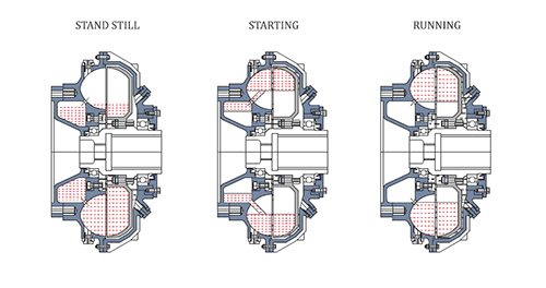
Oil circuit & starting-torque characteristics
Three circuit executions give starting torque from 120–275% of nominal; the delayfil chamber shapes the acceleration curve.

Soft starting across rotating equipment
Need help selecting the right SM size?
Send us your motor rating, speed and driven-machine details and our application engineers will recommend the correct SM, SMD or SM-DX model.